macropad
a 4-key macropad with two rotary encoders and a 0.91" oled, built around a seeed xiao rp2040 - schematic and 2-layer pcb in kicad, a 3d-printed case in fusion 360, and firmware in kmk.
the parts
- a seeed xiao rp2040 as the controller.
- four cherry mx-style switches and two ec11 rotary encoders.
- a 0.91" 128x32 i2c oled.
- two sk6812 mini-e addressable rgb leds.
- a two-piece 3d-printed case.
electrical design
- no matrix and no diodes. each key runs from its own gpio straight to ground (sw1-sw4 on gpio0, 1, 2 and 4), and the firmware reads them with kmk's direct-pin KeysScanner using the internal pull-ups.
- the encoders' a/b channels take gpio26-29, with their common pins to ground.
- the oled sits on a 4-pin header on the rp2040's i2c pins (gpio6 sda, gpio7 scl), powered from 5v.
- the two leds are daisy-chained - gpio3 drives the first led's data in, and its data out feeds the second - so both run from one pin.
- that's all 11 of the xiao's gpio in use. the encoders' push switches aren't wired to a gpio.
pcb
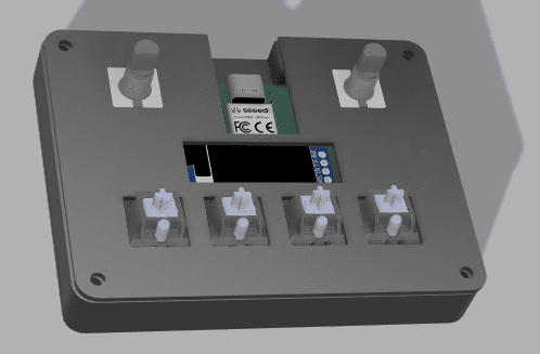
a 2-layer board in kicad, routed on both copper layers. the encoders sit in the top corners with the xiao and the two leds between them, the oled header is in the middle, and the four keys run along the bottom - the same layout the case cutouts follow. a 'xiao here!' note on the silkscreen marks where the controller goes.
case
two printed parts designed in fusion 360: a bottom shell the pcb drops into, with a cutout in the top wall where the xiao's usb-c port sits, and a flat top plate with round holes for the encoder shafts, a window for the oled and four square key cutouts. both parts have matching holes at the four corners. the kicad board is exported as a step with 3d models of the xiao, switches, encoders and oled, and placed in the fusion assembly, so the renders show the real board sitting in the shell under the plate.
firmware
kmk on circuitpython. the four keys send a-d as placeholders, the left encoder is volume up/down and the right is page up/down. the leds run through kmk's rgb extension, and the oled is driven directly with displayio and the ssd1306 driver at i2c address 0x3c, showing a static 'DHIR MACROPAD' label.
what went wrong
the pin map in the firmware doesn't match the board. main.py puts the keys on a0-a3 and the encoders on d6-d9, but on the schematic it's the other way round: the encoders are on a0-a3 (gpio26-29) and the keys are on d6-d9 (gpio0, 1, 2 and 4). it was a pretty fatal mistake - with the pins swapped, the keys and knobs don't do what they should on the real board.
the fix
the pcb is assembled with the xiao, oled, encoders and switches, so the hardware side is done. i still have to fix the firmware by swapping the two pin lists in main.py so it matches the schematic.
what i learned
it's a mistake i won't make again. before i call a board done, i check the firmware's pin map against the schematic.
gallery
the schematic - keys sw1-sw4 on gpio0, 1, 2 and 4 straight to ground, encoder a/b channels on gpio26-29, the oled header on gpio6/7 (sda/scl), and the two sk6812 leds chained from gpio3. the 2-layer layout in kicad - encoders in the top corners, the xiao and both leds between them, the oled header in the middle, and the four switches along the bottom. red traces are front copper, blue are back. the two case parts in fusion 360 - the bottom shell with a cutout in the top wall for the xiao, and the top plate with holes for the encoder shafts, the oled window and four key cutouts. the assembled pcb sitting in the bottom shell, with the top plate beside it. the real board, assembled - xiao, oled, both encoders and all four switches.