jacking bar
a lighter, manufacturable jacking bar for the university of alberta formula sae car - a steel tube with scooped cutouts, validated with fea and built by hand.
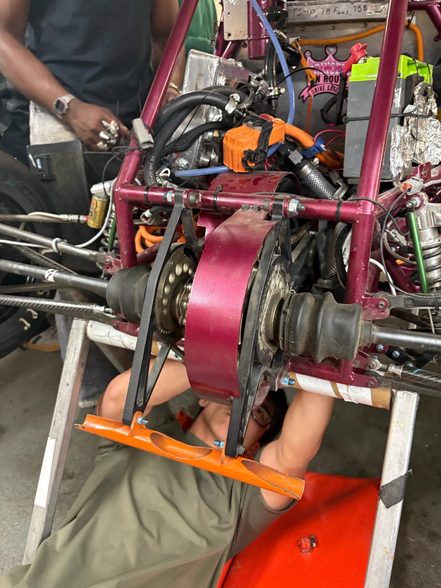
the problem
last year's jacking bar was too heavy, wasn't manufactured properly, failed inspection, and ran into a lot of issues. this year the goal was a new bar designed from the start to be made.
design choices
- a steel tube with large scooped, saddle-shaped cutouts - material comes out where the load path doesn't need it and stays where it does.
- two tabs welded onto the tube that pin to the differential hangers.
- clearance to the differential hangers: the part connecting to the hangers didn't give enough clearance, so the differential hangers were actually hitting the jacking bar. we redesigned the mounting tabs to be a bit longer and differently shaped so everything clears.
fea
- static study in solidworks simulation: peak von mises stress around 186 mpa against a 460 mpa yield strength.
- factor of safety study: a minimum factor of safety of about 2.0.
- the minimum-safety-factor hotspot sat at a sharp cutout edge. stress concentrates at sharp, pointy corners, so that transition got a fillet to spread the load over more material.
- the stress study also showed some edges were too thin and would break, so those got fillets too.
manufacturing
my cnc lathe training wasn't finished, so machining it wasn't an option. instead we made a drawing, printed a stencil from it, wrapped the stencil around the tube, cut the profile with an angle grinder, spray-painted it, and welded on the tabs that pin to the differential hangers.
what went wrong
cutting by hand is never as accurate as the model. following a stencil with a grinder makes clean, consistent curves hard, and small deviations add up along a long profile - the stencil at least meant the shape came from the drawing rather than from freehand marking.
what i learned
- design for manufacturing with the tools you actually have access to, not the ones you wish you had.
- stress concentrates at sharp corners - a fillet is a cheap fix.
- read an fea factor-of-safety plot for where the minimum is, not just what the peak stress is.
- how to make a drawing that someone can actually build from.
gallery
the new jacking bar in the drivetrain assembly - the two welded tabs pin to the differential hangers. the finished bar on the car - painted, with the welded tabs bolted to the differential hangers. close-up of the cutouts - material removed where the load path doesn't need it, with filleted transitions. static fea (von mises) - peak ≈186 mpa against a 460 mpa yield strength. factor of safety study - minimum fos ≈2.0 across the whole bar. the hotspot - stress concentrated at a sharp cutout edge, which is why that transition got a fillet. manufactured by hand - a printed stencil wrapped on the tube, then the cutouts ground out with an angle grinder.