hexacopter motor mounts
3d-printed motor mounts for the uarad university drone team's hexacopter - a twist-lock top plate, a print orientation chosen around the loads, and a lot of lessons about clearances and tolerances.
the problem
each mount holds a motor on the end of a carbon-fibre arm. in the first design, the top plate was held on by three m3 screws threading into the mount casing. a printed prototype showed it couldn't work: the casing left no access to seat a captive nut behind the screw holes, and the fit between printed parts was off enough to cause binding and play.
design choices
- cheap test prints first: before committing to full-strength prints, we ran a quick test print at 5% infill just to check clearances and gaps. it's fast and uses little material, so fit problems show up early instead of on a final part.
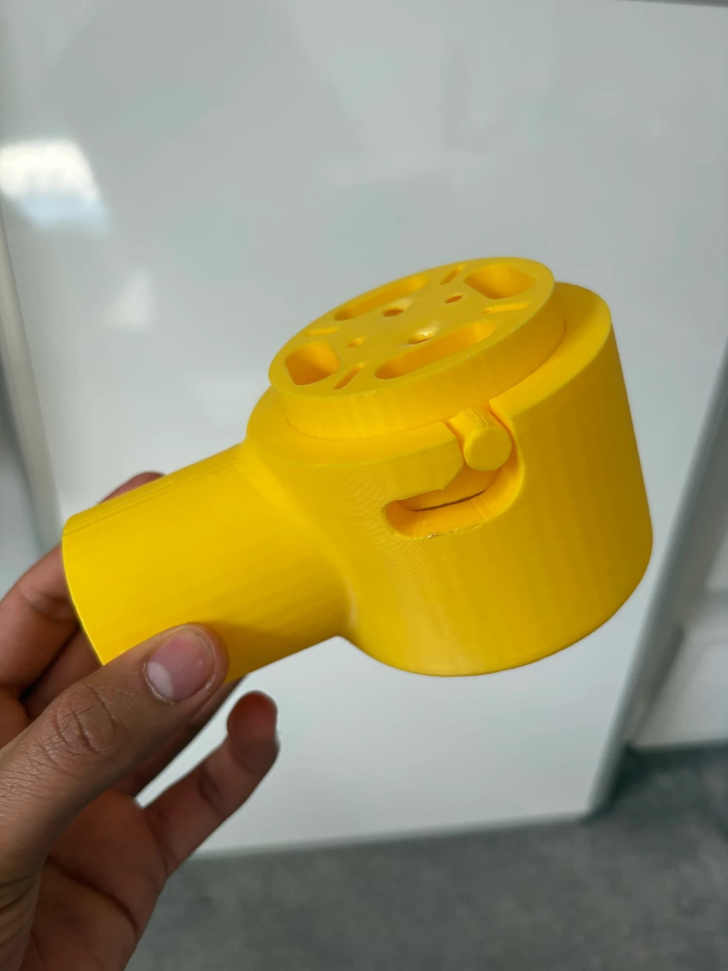
- twist-lock top plate: i redesigned the top plate as a bayonet-style twist-lock with the bottom mount. the top plate uses m4 screws, and the geometry is set so that when the plate twists and locks in, its screw holes line up - the lock does the locating, so the screws aren't fighting for alignment.
- print orientation: fdm parts are weakest between layers, so orientation is a structural decision, not a slicer default. i printed the mount top-down so the layers run horizontally, choosing the layer direction relative to the principal stresses from hand calcs.
- a fillet at the base: i was worried about layers peeling apart where the base plate meets the walls. thinking of stress as lines flowing through the part, i added a solid fillet there so the load has a path across the layer lines instead of a sharp corner to concentrate at.
- infill: pla at about 45% gyroid. strength gains are minimal as you go higher, and gyroid is close to equally strong in every direction, which suits a part loaded from several directions.
- arm socket: i thickened the section where the carbon-fibre arm tubes go in. the tubes are friction-fit and don't budge.
the cutouts
on the mount face there's a central circular recess for the motor's bottom boss and shaft, with four small holes for the motor's mounting screws. around it are four rounded-rectangle cutouts and four narrow diagonal slots, which leave solid cross-shaped spokes running from the motor seat out to the rim. the top plate has a matching pattern. the reasoning: material comes out where it isn't in the load path, which saves weight, while the spokes carry thrust and torque from the motor out to the rim and the arm. the corners are rounded because sharp corners concentrate stress, and pla doesn't tolerate that well. the openings also let air move under the motor and give the motor leads a way through.
what went wrong
- the three-screw top plate (above) - caught by a printed prototype before it went any further.
- the tip at the bottom of the mount was modelled a bit too shallow, so it wasn't going through properly. i made it bigger.
- printed holes came out slightly smaller than modelled - the infill and print shrink pull a hole in. i started measuring real printed parts and feeding the clearances back into cad before committing to final prints.
- the 5% infill test print showed the plate height was a bit too tall, which caused interference with the bottom of the plate. i redesigned the height to fix it, along with the clearances, before the final print.
what i learned
clearances were the big one. almost every problem on this part was a clearance or tolerance problem: the bottom tip too shallow, printed holes coming out undersized, the plate height interfering, and getting the bayonet to twist and lock without binding or play. a part that fits perfectly in cad doesn't fit off the printer - you measure the real part, find the offset, and design it in, and a quick low-infill test print is the cheapest way to find those offsets. i also learned to treat print orientation and infill as structural decisions.
status
after the 5% infill test print, i fixed the clearances and the plate-height interference, then made the final full-strength print (45% gyroid pla). the final mounts went on the hexacopter and we did a test flight.
video
gallery
5% infill test print - top plate seated and twisted into the bayonet slot, with the arm-tube socket in front. 5% infill test print, looking down the mount face - central motor boss recess with four motor screw holes, four rounded cutouts and four diagonal slots, arm-tube socket below.